Home > News > Company News
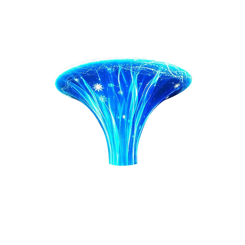
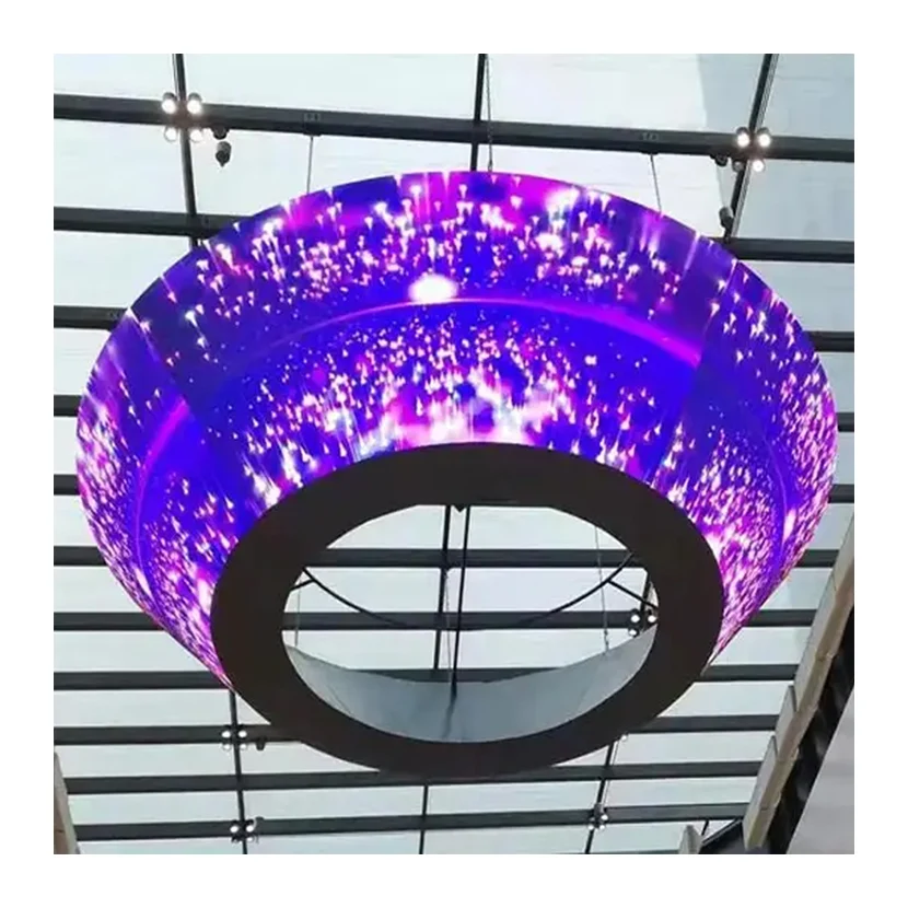
Replacing a damaged module in a shaped LED display is not always as simple as removing one panel and installing another. Unlike standard flat LED screens, custom displays often contain modules with different shapes, dimensions, connection positions, and installation directions.
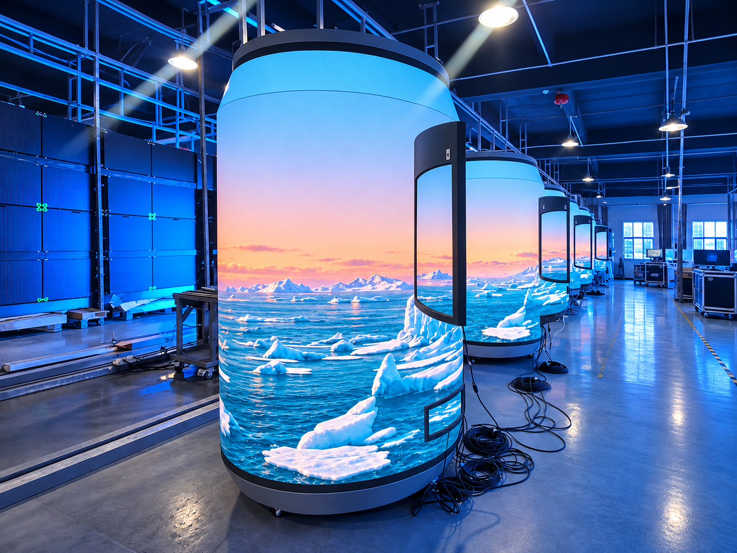
A module designed for the upper section of a spherical screen may not fit the lower section. Even two modules with similar dimensions may have different PCB layouts or connection points.
Without clear identification records, maintenance teams may spend hours checking parts before finding the correct replacement.
A reliable module traceability system helps technicians identify the exact replacement part before starting repair work.
Using the wrong module can create several problems.
Installation problems: Different module shapes or mounting positions may cause gaps, uneven edges, or mechanical interference.
Display differences: Modules from different production batches may have visible brightness or color differences.
Electrical incompatibility: Different PCB revisions, driver ICs, or connector layouts may affect signal transmission and power connections.
Longer maintenance time: Technicians may need to remove and test several modules before finding a suitable replacement.
For commercial installations, these problems can delay reopening, event preparation, or daily advertising operations.
There are three common reasons.
Special-shaped LED displays may use triangular, trapezoidal, curved, or irregular modules. Each module has a specific installation position.
A manufacturer may update the PCB layout, connector position, driver IC, or structural design during production. A newer module may look similar to the original but have different internal specifications.
If module labels, production dates, and revision numbers are not recorded, maintenance teams cannot easily determine whether a replacement part matches the original configuration.
Therefore, module identification should begin during production rather than after a screen develops a fault.
A practical traceability system should connect each physical module with its position and technical information.
Divide the screen into clear sections and assign each module a unique identification code.
For example, a spherical LED display can use:
S01: Upper section
S02: Upper-middle section
S03: Lower-middle section
S04: Bottom section
Each section can then have individual module numbers, such as S01-M01 or S01-M02.
For a letter-shaped or geometric LED display, numbering can follow the screen's structural layout, from left to right or from top to bottom.
Every module should have a revision record.
Important information includes:
Module model and pixel pitch
PCB revision number
Production batch number
Connector type and position
Driver IC model
Manufacturing date
For example, a replacement request may specify: S02-M04, P2.5, PCB Rev B, Batch 2026-08.
This makes it easier for the manufacturer to identify the required configuration.
Create a spreadsheet or database containing the module code, installation position, production revision, and replacement history.
A QR code or barcode can also be attached to the module or its packaging. Technicians can scan it to access the corresponding technical information.
The record should be updated whenever a module is replaced or its position changes.
Correct identification is only the first step. The replacement module should also pass several checks.
Physical inspection: Compare the module's dimensions, shape, mounting holes, thickness, and connector positions with the original.
Electrical inspection: Check the voltage requirements, pin arrangement, signal interface, and driver IC compatibility.
Visual inspection: Display red, green, blue, white, and grayscale test patterns. Compare brightness, color temperature, and pixel performance with surrounding modules.
Position verification: Confirm that the replacement module is installed in the correct direction and assigned to the correct receiving-card output.
After installation, run the complete display and inspect the repaired area from different viewing angles.
For curved and spherical screens, also check whether the replacement follows the original surface smoothly without visible gaps or uneven transitions.
Module traceability should cover more than the LED surface itself.
A useful maintenance record should include:
LED modules and PCB revisions
Receiving cards and firmware versions
Power supply models and output specifications
Signal and power cables
Mounting brackets and fixing accessories
Screen layout and connection diagrams
Keeping these records together helps technicians identify whether a problem comes from the module, control system, power supply, or physical installation.
Different screen structures require different identification methods.
Spherical LED displays: Divide the spherical surface into horizontal or vertical sections. Record each module according to its position and installation direction.
Letter-shaped LED displays: Assign codes to individual letters and separate curved or straight sections. This prevents modules from being installed in the wrong area.
Geometric LED displays: Use structural drawings to identify triangular, trapezoidal, and polygonal modules. Position codes should match the original assembly drawings.
For example, when replacing a damaged module on a custom exhibition screen, the technician can check the position code and revision record before requesting a replacement. This reduces unnecessary disassembly and helps maintain consistent display performance.
Not always. Pixel pitch is only one specification. The module shape, PCB design, connector layout, driver IC, and control configuration must also be compatible.
Check the original project drawings, module dimensions, PCB markings, connector positions, and production records. If necessary, send clear photos to the manufacturer for technical identification.
Using modules from the same batch is generally preferable because it can reduce brightness and color differences. If the original batch is unavailable, additional compatibility checks and color calibration may be necessary.
Keep spare modules, installation drawings, position codes, revision records, and control-system configuration files. These materials make future maintenance much easier.
Founded in 2014, Shenzhen Toosen Optoelectronics Co., Ltd. specializes in the research, development, manufacturing, and engineering of LED display products.
TOOSEN provides customized LED display solutions, including spherical, cylindrical, bottle-shaped, flexible, and other irregular LED displays. With OEM and ODM capabilities, the company can develop screen structures and module designs according to different project requirements.
Its services cover product design, manufacturing, installation guidance, technical support, and after-sales maintenance. Products have also obtained international certifications, including CE, FCC, and RoHS.
For customized projects, clear module layouts, component specifications, and production information help customers manage future repairs and replacement requirements.
Whether you are planning a spherical LED display, a creative retail installation, or a complex geometric screen, TOOSEN can provide technical support to help build a suitable display solution.
Visit the official website: https://www.toosenled.com/
 EN
 AR
 BG
 HR
 CS
 DA
 NL
 FI
 FR
 DE
 EL
 HI
 IT
 JA
 KO
 NO
 PL
 PT
 RO
 RU
 ES
 SV
 TL
 ID
 SR
 UK
 VI
 ET
 HU
 TH
 TR
 FA
 AF
 MS
 GA
 HY
 AZ
 MN
 UZ