Home > News > Industry News
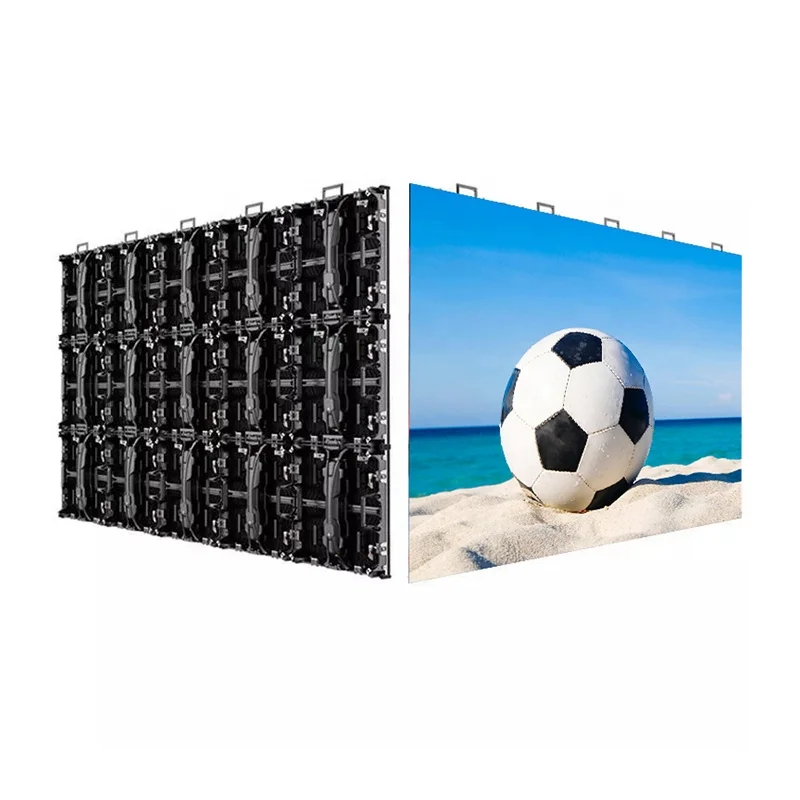
The wiring logic of an irregular LED display is fundamentally the same as a standard rectangular LED screen because both systems rely on power cables and signal cables. However, irregular LED displays — such as spherical, cylindrical, wave-shaped, and polygonal screens — require more advanced wiring design due to their non-standard structures.
Engineers must pay special attention to cable routing, topology design, signal synchronization, and physical installation details.
An irregular LED screen uses two core wiring systems:
Power cables deliver electricity from the AC power source to the LED modules and control system.
The workflow is:
220V AC power → Power distribution cabinet → Switching power supply → 5V DC output → LED modules and control cards
Signal cables transmit display data from the control system to the screen modules.
The signal path usually follows:
Sending card → Receiving card → LED modules
Depending on the project, engineers may use:
Irregular LED displays cannot expose visible cables because exposed wiring affects the visual appearance.
Therefore, engineers usually route all cables inside the supporting structure.
Before installation, teams should:
Good pre-planning dramatically reduces installation problems later.
The standard power workflow includes:
Correct polarity is critical.
Reversed polarity may damage LED modules or control systems instantly.
Each cabinet or display zone should ideally use an independent power feed from the distribution cabinet.
This design reduces voltage drop caused by long daisy-chain power connections.
Engineers typically use copper-core cables larger than 4 mm².
The system should support approximately:
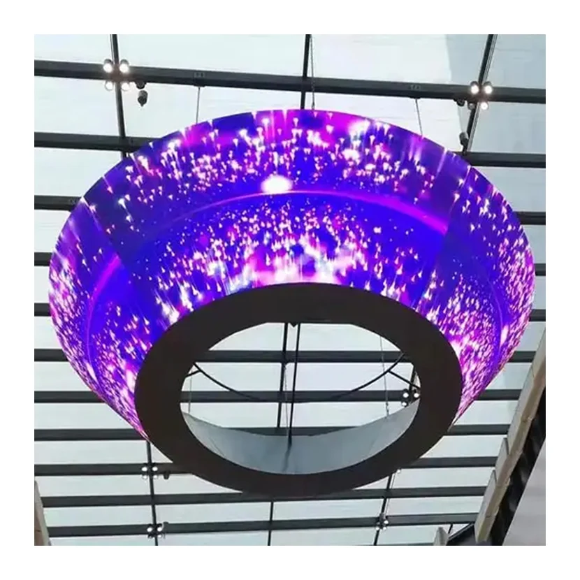
Closed structures such as spherical LED screens trap heat easily.
Therefore, installers should place at least two cooling fans per square meter inside enclosed structures.
In addition, engineers should separate fan wiring from signal wiring to minimize interference.
Most LED systems use daisy-chain signal transmission.
The signal flow must remain consistent:
Sending card → Module IN port → Module OUT port → Next module IN port
The chain continues sequentially throughout the display.
Typical LED module ribbon cables contain:
| Signal | Function |
|---|---|
| ABCD | Row selection signals |
| STB / LAT | Latch signal |
| CLK / CK | Clock signal |
| R1 / R2 / G1 / G2 | Display data signals |
These signals must remain stable for proper synchronization.
Engineers usually wire spherical screens symmetrically around the equator line.
Signal cables cascade vertically along longitudinal directions, while each latitude ring connects sequentially.
Spherical displays commonly use:
The gap between modules should remain under 2 mm.
Upper hemisphere wiring requires extra cable slack to prevent gravity from pulling connectors loose over time.
Modules connect around the cylinder circumference ring by ring.
However, engineers must avoid forming a closed signal loop because ring topology may create data conflicts.
Typically:
This keeps the installation clean and organized.
Flexible module cables should never bend beyond 90 degrees.
Excessive bending may break internal conductors.
The three most important synchronization signals are:
These lines should remain as equal in length as possible.
If necessary, engineers use serpentine routing to compensate for path differences.
Even a 5 cm timing difference on a CLK line may cause:
Teams usually mark module positions with surveying equipment before wiring begins.
Installation tolerance should remain within 1 mm.
Polygon edges should use aluminum alloy frames to protect connectors from accidental impacts.
For irregular LED displays, star topology works better than long daisy chains.
Ideally:
This structure reduces:
Ethernet cables become unreliable beyond approximately 70 meters.
Long-distance installations should switch to:
Fiber transmission provides better stability and stronger resistance to electromagnetic interference.
Stable synchronization requires proper electrical engineering.
Best practices include:
These measures reduce signal reflection and suppress electrical noise.
Before powering on the system, engineers should verify every item carefully.
| Inspection Item | Standard |
|---|---|
| Power polarity | No reverse connection or short circuit |
| Signal direction | Correct forward data flow |
| Cable separation | Signal and power cables routed separately |
| Connector stability | No loose ribbon cables or terminals |
| Network topology | No circular signal loops |
| Grounding | All cabinets and controllers share common ground |
The wiring principles of irregular LED displays can be summarized as:
Although irregular LED displays appear much more complex than traditional rectangular screens, proper 3D planning and organized cable management make installation far more manageable.
The key is to follow the predefined numbering sequence carefully and avoid temporary on-site rewiring whenever possible.
 EN
EN
 AR
AR
 BG
BG
 HR
HR
 CS
CS
 DA
DA
 NL
NL
 FI
FI
 FR
FR
 DE
DE
 EL
EL
 HI
HI
 IT
IT
 JA
JA
 KO
KO
 NO
NO
 PL
PL
 PT
PT
 RO
RO
 RU
RU
 ES
ES
 SV
SV
 TL
TL
 ID
ID
 SR
SR
 UK
UK
 VI
VI
 ET
ET
 HU
HU
 TH
TH
 TR
TR
 FA
FA
 AF
AF
 MS
MS
 GA
GA
 HY
HY
 AZ
AZ
 MN
MN
 UZ
UZ