Home > News > Industry News
A geometric shaped LED stage display may contain triangles, diamonds, trapezoids, rectangles, and other irregular sections. These sections can be installed at different angles and distances from one another.
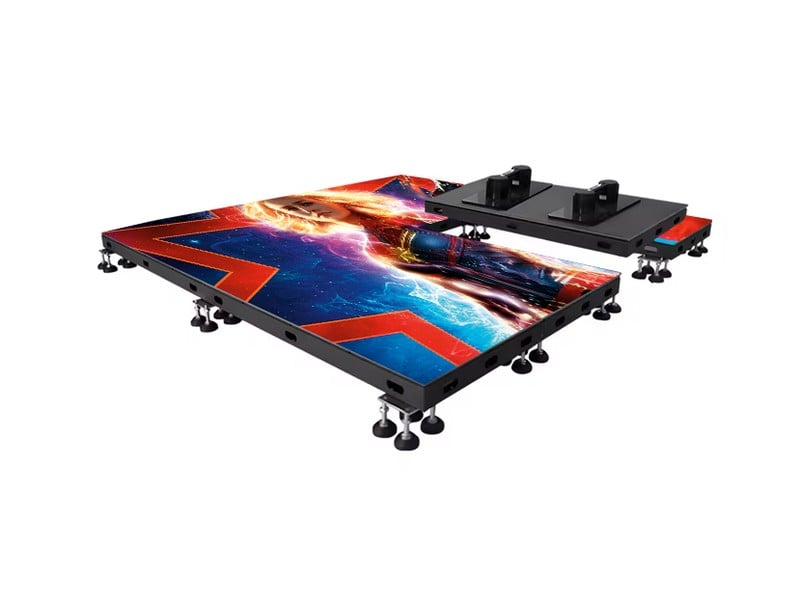
The challenge is making all sections display the correct part of one video. If the content mapping is incorrect, a moving graphic may stop at the edge of one section, appear in the wrong position, or move in an unexpected direction.
This problem often appears during installation or when the stage team changes the playback content. Even when every LED section works correctly, the overall image can still look broken.
For a customized stage, section numbering should be planned before the display is installed and the final content is produced.
Incorrect numbering can cause several practical problems.
First, the image may appear on the wrong section. For example, a triangle intended to display the left side of a graphic may show the right side instead.
Second, motion effects can lose continuity. A line that should travel from one geometric section to another may jump, reverse direction, or disappear into an empty space.
Third, troubleshooting becomes slower. Without a clear numbering system, technicians may need to test individual cabinets repeatedly to identify which physical section corresponds to a controller output.
These problems can delay rehearsals, increase commissioning time, and create additional work for content designers and installation teams.
There are three common causes.
Physical layout and software layout do not match. The installation drawing may show sections from the audience's perspective, while the control software lists them in another order.
Signal connections are recorded incorrectly. A processor output or receiving-card connection may feed a different section than the technician expects.
Content is designed for the wrong canvas. Designers may create a rectangular video without accounting for the actual positions, angles, and gaps between the LED sections.
A reliable mapping plan must connect three things: the physical screen, the control system, and the content canvas.
Start with the final stage drawing or a measured installation layout. Mark every separate LED section and give it a unique ID.
A simple numbering sequence could be:
S01: upper-left triangle
S02: upper-center diamond
S03: upper-right triangle
S04: lower-left trapezoid
S05: center rectangle
S06: lower-right trapezoid
These IDs are examples, not a universal standard. Choose a system that is easy for the installation and content teams to understand.
Number sections consistently from the audience's viewing position. Record each section's shape, dimensions, orientation, and physical location.
Build a mapping table before connecting the complete system.
| Section ID | Shape | Position | Connection reference |
|---|---|---|---|
| S01 | Triangle | Upper left | Output A |
| S02 | Diamond | Upper center | Output B |
| S03 | Triangle | Upper right | Output C |
| S04 | Trapezoid | Lower left | Output D |
The connection references above are illustrative. Actual processor outputs and receiving-card assignments must be confirmed on site.
If one section contains multiple cabinets or receiving cards, record their internal order separately. This prevents a correct section-level map from hiding a wiring or scanning-order problem inside the section.
The content canvas represents the complete visual composition. It does not necessarily need to be a single solid rectangle on the physical stage.
Place each section in the canvas according to its actual position and orientation. Then define the pixel boundaries for each section.
For example, if S01 occupies a particular rectangular region in the software canvas, its visible triangle may use only part of that region. The unused pixels must be treated as an inactive area or masked region where appropriate.
For irregular installations, do not assume that the order of the physical sections automatically matches their order in the content file.
Use the section map and connection table to configure the controller and receiving cards.
Display a simple test pattern on one section at a time. Confirm that S01 lights up when S01 is selected, then repeat the process for the remaining sections.
If a section displays the wrong pattern, check its signal path and mapping configuration before changing the entire content canvas.
For more complex installations, keep a record of the processor configuration, cabinet coordinates, firmware versions, and any section-specific adjustments.
Do not rely on a single full-screen video to confirm that the system is ready.
Use three separate tests.
Test 1: Section identification. Display a different number or solid color on each section. Confirm that the physical section matches its assigned ID.
Test 2: Boundary alignment. Play a grid, diagonal line, or moving line across the complete composition. Check whether the image follows the intended positions and directions across adjacent sections.
Test 3: Playback verification. Run the actual show content at the intended resolution and frame rate. Check for reversed motion, misplaced graphics, black areas, unexpected cropping, and visible timing differences.
Record each test result and photograph any problems. If a correction is made, repeat the affected tests before final acceptance.
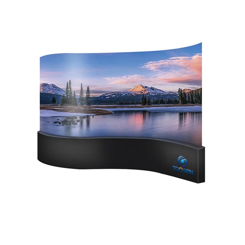
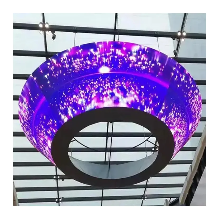
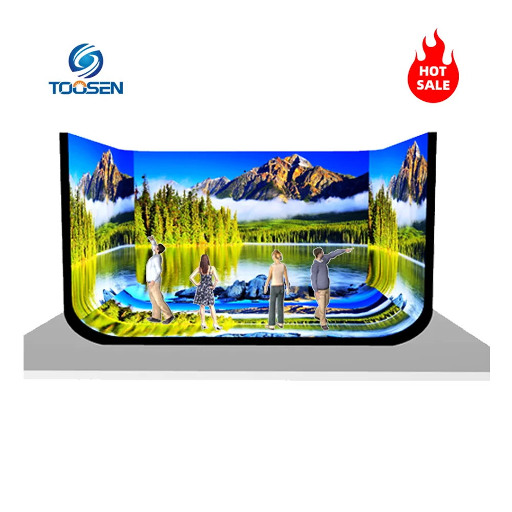
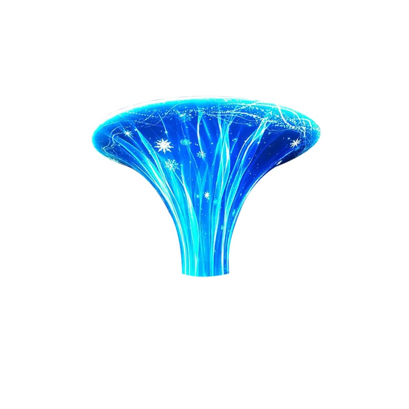
The physical design affects how content must be mapped. Triangular and polygonal screens need careful coordinate planning, while curved or flexible sections may require additional attention to orientation and image distortion.
TOOSEN provides customized shaped LED display solutions for different screen geometries and installation requirements. When planning a stage project, confirm the section dimensions, pixel pitch, cabinet arrangement, control system, maintenance access, and required content format before production.
A useful handover package should include the final section drawing, numbering table, signal connection diagram, mapping configuration, test patterns, and approved playback file.
Consider an indoor stage with six LED sections arranged around a central performance area. The designer wants a single animated graphic to travel from the upper-left triangle through the center and toward the lower-right trapezoid.
The installation team first labels all six sections from the audience's perspective. The control technician then records the signal connections and maps each section to the correct pixel coordinates.
During testing, a moving line reveals that S03 displays part of the graphic intended for S02. Instead of redesigning the entire animation, the team checks the section mapping and corrects the relevant assignment.
After correction, the team repeats the boundary test and plays the complete animation. The final configuration is saved and documented for future maintenance.
This workflow is suitable for DJ stages, concert backdrops, exhibition installations, and other projects using multiple geometric LED sections.
Number them during design and verify the IDs during installation. Update the drawing if the actual layout changes.
No. The required outputs depend on the screen's pixel load, controller capacity, receiving-card architecture, and signal distribution design.
The physical section arrangement, software coordinates, screen orientation, or signal mapping may not match the design file. Check each section with an identification pattern before adjusting the animation.
Provide the final layout drawing, section ID table, connection diagram, controller configuration, content canvas specifications, test records, and approved playback files.
TOOSEN offers customized shaped LED display solutions. Project requirements should be confirmed in advance, including the screen geometry, dimensions, pixel pitch, installation method, control system, and content mapping requirements.
A clear numbering system turns a complex geometric LED stage into a manageable installation. By matching physical section IDs, signal connections, and content coordinates before the event, project teams can reduce mapping errors and make future troubleshooting much easier.
 EN
 AR
 BG
 HR
 CS
 DA
 NL
 FI
 FR
 DE
 EL
 HI
 IT
 JA
 KO
 NO
 PL
 PT
 RO
 RU
 ES
 SV
 TL
 ID
 SR
 UK
 VI
 ET
 HU
 TH
 TR
 FA
 AF
 MS
 GA
 HY
 AZ
 MN
 UZ