Home > News > Industry News
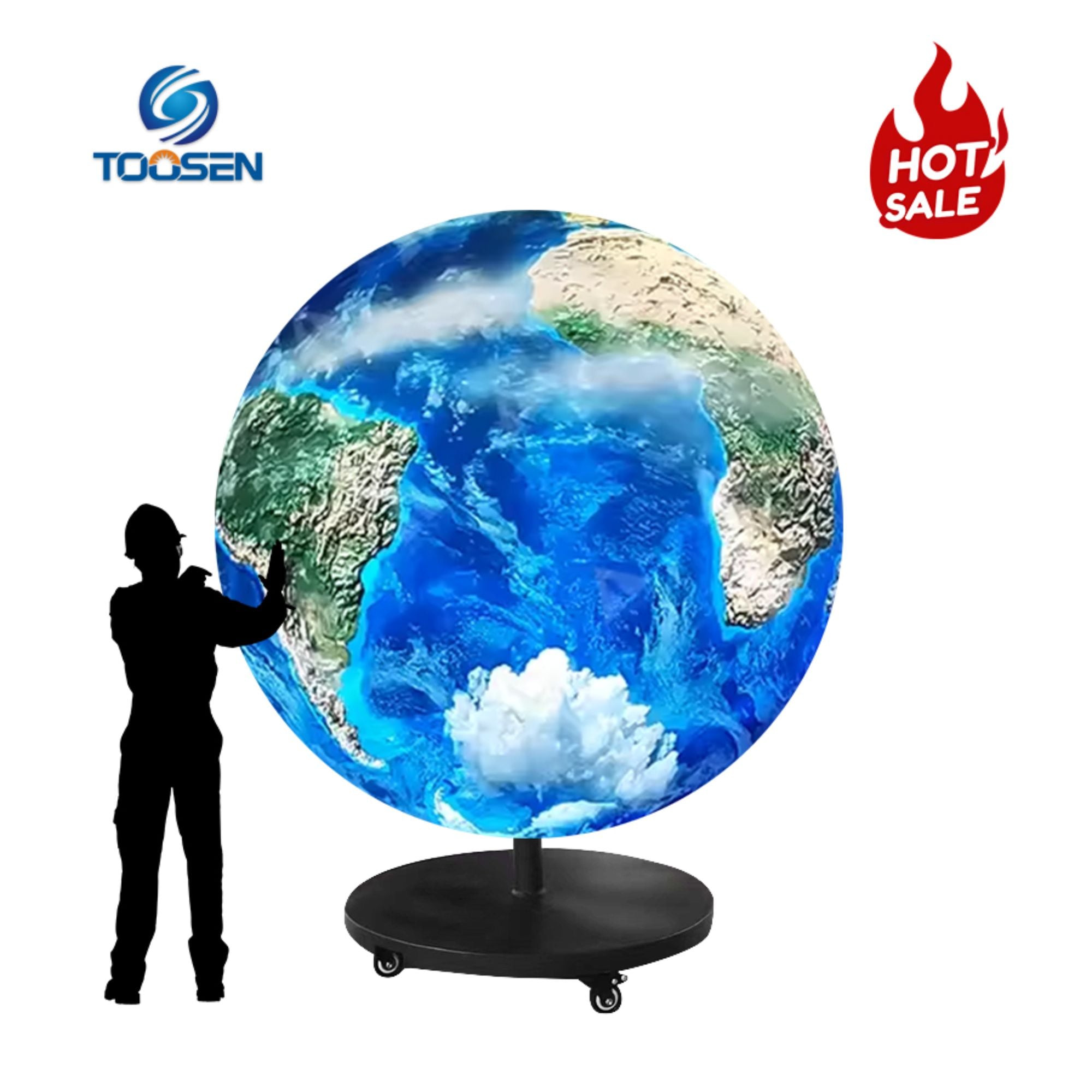
A sphere LED display can show images and videos from every direction, but getting the content to appear correctly requires more than uploading a video. Each physical section must match its position in the control software. If the numbering, signal sequence, or mapping coordinates are incorrect, images may appear in the wrong location, cross section boundaries, or become distorted.
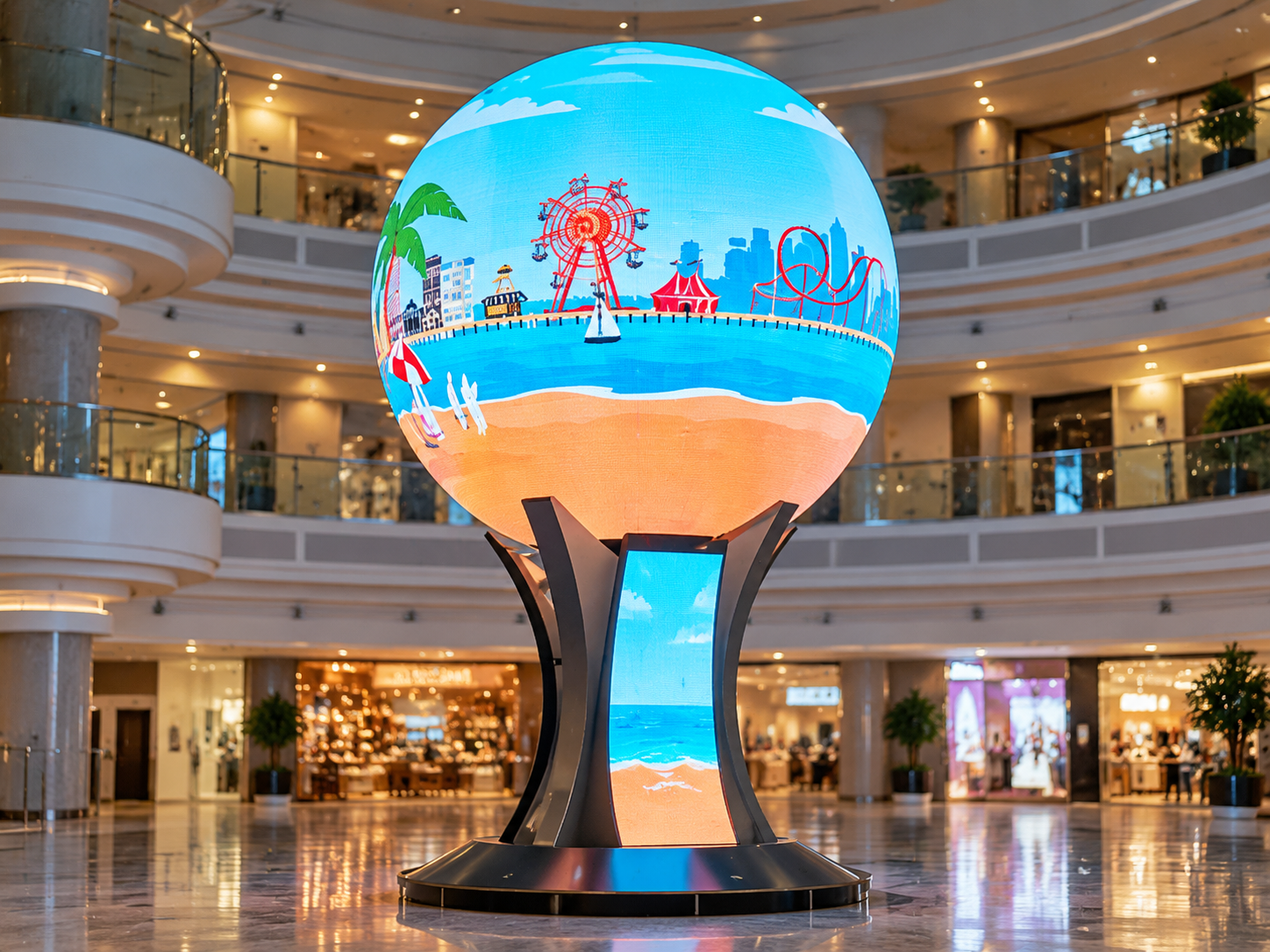
For installers, system integrators, and project buyers, a clear mapping plan helps reduce commissioning time and makes future maintenance easier. This guide explains how to number sections, configure content mapping, and verify playback on a spherical LED display.
Unlike a flat LED screen, a sphere LED display has a curved surface made from multiple modules or sections. Each section occupies a different position and viewing angle.
Without a correct mapping configuration, common problems include:
Text or logos appearing across the wrong sections.
Images becoming stretched near the top or bottom of the sphere.
One section displaying content intended for another area.
Videos showing visible breaks at module boundaries.
Replacement modules requiring time-consuming reconfiguration.
These problems can affect visual quality and delay project acceptance. A numbering system that connects the physical layout, wiring sequence, and software coordinates helps technicians locate errors quickly.
Before opening the control software, create a physical section map. The numbering method should be agreed upon by the installation and programming teams.
Choose a clear starting point, such as the front-facing center line and the bottom section. Mark the sphere's orientation so that everyone uses the same reference when viewing the display.
For example, the team may label the bottom-front section S01 and continue around the lower ring as S02, S03, and S04. The next ring can use S11, S12, S13, and S14.
This is only an example. The actual numbering must follow the sphere's module layout and the manufacturer's drawings.
Each section should have a unique identifier. Record its physical position, receiving-card assignment, signal connection, and corresponding software coordinate.
|
Section ID |
Physical position |
Verification item |
|---|---|---|
|
S01 |
Bottom-front |
Confirm first mapped section |
|
S02 |
Bottom-right |
Check signal sequence |
|
S11 |
Middle-front |
Verify image alignment |
|
S21 |
Upper-front |
Check polar distortion |
For complex spheres, also record cable labels and the direction of signal transmission. Do not assume that the electrical connection order always matches the physical numbering order.
Open the LED control software and load the correct screen configuration. Set the actual display resolution, module arrangement, and receiving-card parameters according to the approved configuration file.
Then assign each physical section to its corresponding mapped area. If the software uses pixel coordinates instead of section names, keep a separate coordinate table linked to the physical labels.
For further background on the control system and spherical structure, see the TOOSEN spherical LED display structure guide.
Incorrect mapping does not always mean that an LED module is damaged. Before replacing hardware, identify whether the problem comes from the software configuration, signal routing, or physical installation.
Wrong section displays the image: Check the section numbers and receiving-card assignments. Compare the physical cable route with the saved configuration.
Image appears stretched or distorted: Check whether the content has been prepared for the sphere's actual pixel layout. A standard rectangular video may require spherical warping or geometric correction to look natural on the curved surface.
A visible break appears between sections: Check module alignment, section coordinates, and the continuity of the test image. Also confirm that the content itself does not contain an unintended gap.
One section remains black: Check its power supply, signal cable, receiving card, and configuration. If the hardware works normally but the image appears in the wrong place, investigate mapping before replacing components.
For additional troubleshooting steps, refer to the sphere LED screen loading and signal troubleshooting guide.
A successful software configuration does not guarantee that every part of the sphere displays content correctly. Run a structured playback test before delivery or final acceptance.
Display a test pattern with clearly numbered sections. Check each physical area against the mapping table.
Confirm that S01 displays the correct number, S02 displays the next assigned number, and so on. This test quickly identifies swapped sections and incorrect coordinates.
Play a grid pattern with continuous horizontal and vertical lines. Observe the sphere from several viewing angles.
Check whether lines connect correctly across section boundaries and whether any area shows unexpected gaps, offsets, or stretching.
Display solid red, green, blue, white, and black patterns. Follow these with grayscale gradients.
Look for dark sections, abnormal colors, brightness differences, and visible banding. If a section looks different, check its calibration settings as well as its mapping.
Play a video containing moving objects, text, logos, and changes in direction. Watch whether objects move naturally across the spherical surface without jumping between sections.
Run the test for an agreed period and record any signal loss, frozen images, flickering, or synchronization issues. The duration should reflect the project's acceptance requirements.
Save the approved mapping file and configuration backup. Restart the playback system, reload the saved configuration, and repeat the key tests.
This final step helps confirm that the display can recover its correct layout after a restart rather than relying on temporary settings.
Several components work together to produce correct playback on a sphere LED display:
LED modules: Form the curved display surface and determine the physical section layout.
Receiving cards: Distribute image data to the assigned display areas.
Sending card and LED processor: Handle image transmission, screen configuration, and input signals.
Control software: Defines the screen layout, pixel coordinates, and mapping parameters.
Signal and power cables: Maintain reliable communication and stable operation.
The exact configuration depends on the screen size, pixel pitch, module design, and control system. Before installation, confirm that the mapping file matches the actual hardware rather than relying on a configuration from a different project.
Consider a shopping mall installing a spherical LED display in its central atrium. The sphere will play product advertisements, seasonal animations, and brand videos visible from several directions.
During commissioning, the team labels each physical section and records the receiving-card assignments. A numbered test pattern reveals that one upper section displays content intended for a neighboring area.
Instead of replacing the LED modules, the technicians compare the cable sequence with the mapping table and correct the software assignment. They then test grid alignment, color consistency, and moving video from multiple viewing positions.
Finally, they save the corrected configuration and verify playback again after restarting the system.
This workflow helps avoid unnecessary hardware replacement and gives the maintenance team a reliable reference for future repairs.
Q1: Can I use a normal rectangular video on a sphere LED display?
Yes, depending on the control system and content format. However, the video may need spherical mapping, warping, or other geometric correction to appear natural across the curved surface.
Q2: Should section numbers follow the signal cable sequence?
Not necessarily. Physical labels, cable sequence, and software coordinates must be documented separately and matched correctly. The numbering method should follow the approved layout and wiring plan.
Q3: Why does the content look correct on a computer but wrong on the sphere?
Possible causes include an incorrect screen resolution, wrong receiving-card assignments, mismatched mapping coordinates, or missing geometric correction.
Q4: Do I need to test every section individually?
Yes. Individual section identification helps locate mapping errors that may be difficult to detect when playing a full video. Follow this with whole-screen playback testing.
Q5: What should be saved after commissioning?
Keep the final mapping file, screen configuration, section numbering diagram, cable layout, receiving-card assignments, and playback test results. These records simplify maintenance and future system recovery.
TOOSEN specializes in LED display solutions, including spherical LED displays and customized screen structures. Different projects may require different diameters, pixel pitches, module arrangements, and control configurations.
For reliable content mapping, the physical design, receiving-card layout, and software configuration should be confirmed together before shipment. Clear documentation and systematic playback testing help integrators reduce installation errors and deliver a consistent 360-degree viewing experience.
Explore the TOOSEN spherical LED display product page to learn more about available configurations and customization options.
 EN
 AR
 BG
 HR
 CS
 DA
 NL
 FI
 FR
 DE
 EL
 HI
 IT
 JA
 KO
 NO
 PL
 PT
 RO
 RU
 ES
 SV
 TL
 ID
 SR
 UK
 VI
 ET
 HU
 TH
 TR
 FA
 AF
 MS
 GA
 HY
 AZ
 MN
 UZ