Home > News > Industry News
An LED sphere display creates a 360-degree viewing experience, but displaying content correctly across a curved surface requires more than uploading a standard video.
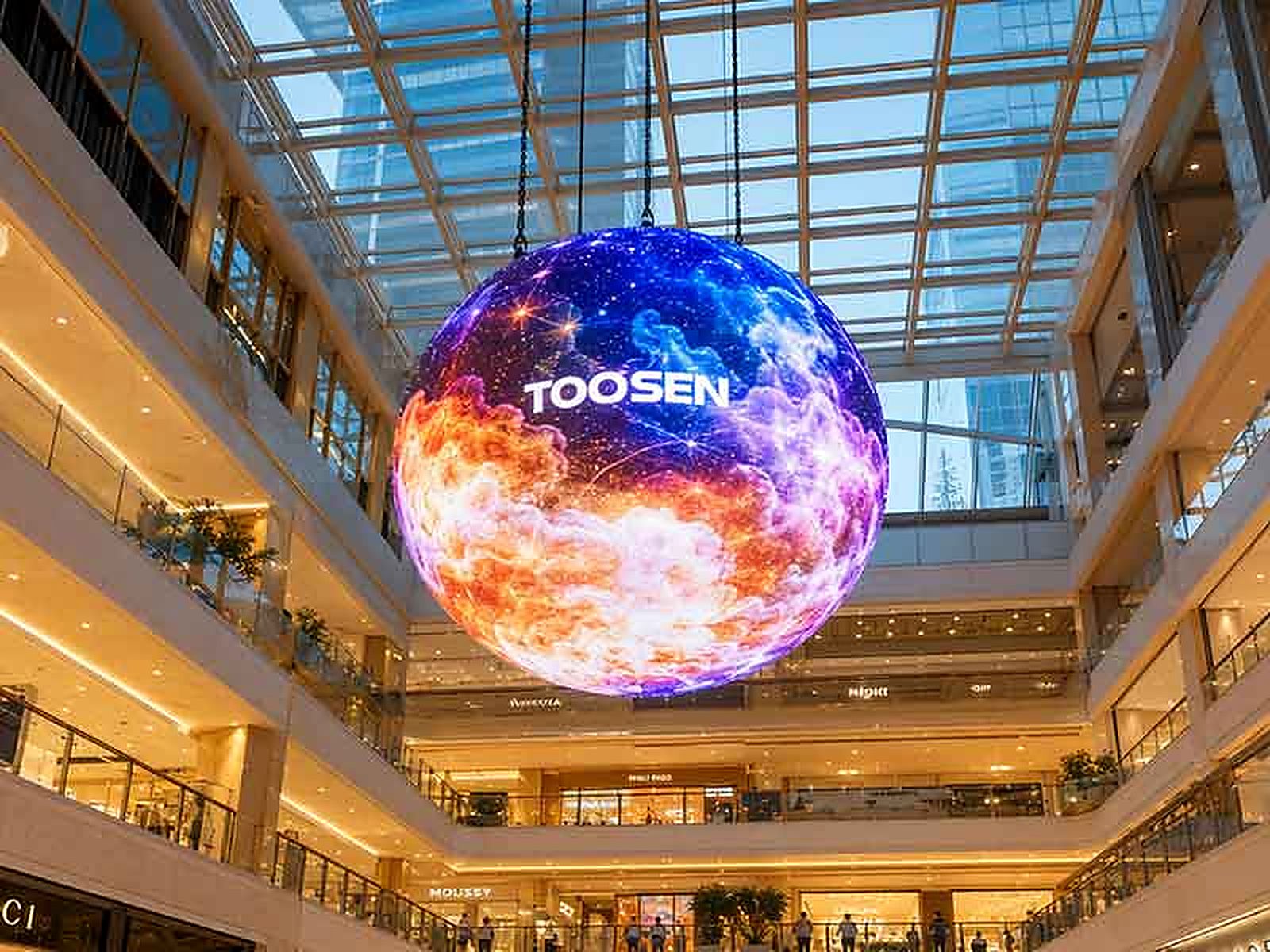
When flat images or videos are transferred directly to a spherical LED screen, some areas may appear stretched, compressed, or incorrectly positioned. Circles may look oval, straight lines may become curved, and text may lose its original proportions.
These problems are usually related to pixel mapping and content formatting rather than defective LED modules.
For projects involving brand logos, product images, maps, or detailed animations, incorrect mapping can affect the entire visual presentation.
Pixel mapping determines how each image pixel corresponds to its physical position on the LED display.
On a flat LED wall, the pixel arrangement usually follows a simple rectangular grid. A spherical LED display has a different structure because its surface curves in every direction.
Incorrect mapping can cause several visible problems:
Image stretching: Objects near the upper or lower sections appear wider or narrower than intended.
Text distortion: Letters lose their original proportions, making information difficult to read.
Uneven graphics: Circular patterns and geometric shapes no longer look balanced.
Content misalignment: Images do not connect correctly across module boundaries.
Animation errors: Moving objects may appear to jump or change shape when crossing different sections.
These issues become more noticeable when the screen displays detailed graphics or content that moves around the entire sphere.
There are three common reasons.
A standard video uses a rectangular coordinate system, while a spherical surface requires coordinates that follow its three-dimensional geometry.
Directly transferring a flat image without proper conversion can produce uneven proportions.
The physical arrangement of LED modules follows the shape of the sphere. Depending on the design, the number and position of pixels can vary between different sections.
Therefore, the software must understand the actual pixel layout rather than assume that the screen is a regular rectangular display.
The input video resolution must match the configured screen canvas and mapping file.
If the source resolution, controller settings, or mapping coordinates do not match the physical display, images may be cropped, shifted, or stretched.
Before adjusting the content, confirm the actual screen structure and total resolution.
Step 1: Create a Spherical Mapping File
Start with the physical dimensions and pixel layout of the LED sphere. Divide the surface into the correct display sections and assign each section its corresponding pixel coordinates.
The mapping file should match the actual module arrangement.
Step 2: Apply Spherical Coordinate Conversion
Use suitable content processing software to convert flat images into a format designed for spherical playback.
Depending on the display design, this may involve UV mapping or other geometric transformation methods.
The purpose is to compensate for differences between flat image coordinates and the curved screen surface.
Step 3: Adjust Individual Display Sections
Check whether images remain continuous across module boundaries.
If one section appears shifted or stretched, review its coordinates and correction parameters instead of changing the entire image randomly.
Step 4: Match the Input Resolution
Configure the video processor and LED control system according to the actual screen resolution.
Check the input signal, output canvas, receiving card configuration, and mapping file together.
A successful mapping setup should be verified with different test patterns rather than one ordinary video.
Here are four useful checks:
| Test Content | What to Check |
|---|---|
| Grid pattern | Pixel alignment and geometric consistency |
| Circular patterns | Whether circles remain visually balanced |
| Text and logos | Letter proportions and graphic distortion |
| Rotating animation | Image continuity across the entire sphere |
First, display a grid pattern and inspect the upper, lower, and middle sections.
Next, play a circular graphic. If it becomes noticeably oval or uneven, review the mapping parameters.
Then, test logos and text at different positions. This helps identify areas where the image needs further correction.
Finally, play a rotating globe or other continuous animation. Observe whether objects move smoothly across different sections without sudden jumps or visible breaks.
For a complete inspection, repeat the test from several viewing positions around the sphere.
Pixel mapping depends on both the physical display and its control system.
LED Modules: Flexible or custom-shaped LED modules create the curved surface. Their physical arrangement determines the pixel coordinates used by the mapping software.
Receiving Cards: These cards distribute image data to individual display sections. Incorrect configuration can cause image displacement or missing content.
Video Processor: The processor handles input signals, resolution settings, scaling, and content output.
Playback Computer: The computer runs the content and mapping software. Its output resolution and video format must be compatible with the control system.
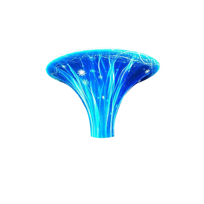
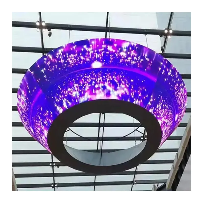
For different project requirements, buyers can explore TOOSEN Spherical LED Display Solutions, which support customized diameters and pixel pitches from P1.2 to P10.
Consider a shopping mall installing a 2-meter spherical LED display in its central atrium.
The screen is designed to show brand advertisements, rotating product images, and promotional animations.
During the initial test, the logo looks correct on the front section but becomes stretched when it moves toward the upper part of the sphere.
The engineering team first checks the physical pixel layout and mapping configuration. They then adjust the spherical content coordinates and test the corrected graphics across different sections.
After adjustment, the team plays several types of content, including logos, circular graphics, and rotating animations.
This process helps ensure that the display presents continuous and visually balanced images from different viewing directions.
Q1. What is pixel mapping on an LED sphere display?
Pixel mapping assigns image coordinates to the physical LED pixels on a spherical surface, allowing content to display in the correct positions.
Q2. Can I use ordinary MP4 videos on a spherical LED screen?
Yes, but the video may need to be converted or adjusted using spherical mapping software before playback.
Q3. Why does text look stretched on a spherical LED display?
This usually happens when flat content is transferred without sufficient geometric correction or when the mapping configuration does not match the physical screen layout.
Q4. How can I check whether pixel mapping is correct?
Use grid patterns, circles, text, logos, and rotating animations. Check image proportions and continuity across different sections.
Q5. Does pixel pitch affect content mapping?
Yes. Pixel pitch determines the physical distance between pixels and contributes to the total screen resolution. The mapping file must reflect the actual pixel arrangement.
TOOSEN specializes in spherical LED displays and customized special-shaped LED solutions for commercial and professional applications.
With different screen diameters, pixel pitches, and indoor and outdoor configurations, TOOSEN can provide solutions according to project requirements.
Our engineering team focuses on module arrangement, structural design, control system configuration, and display testing to help customers achieve reliable visual performance.
From product selection to installation and technical support, TOOSEN works with customers to develop spherical LED display solutions for shopping malls, exhibitions, museums, and entertainment venues.
Visit TOOSEN to explore more spherical LED display solutions.
 EN
 AR
 BG
 HR
 CS
 DA
 NL
 FI
 FR
 DE
 EL
 HI
 IT
 JA
 KO
 NO
 PL
 PT
 RO
 RU
 ES
 SV
 TL
 ID
 SR
 UK
 VI
 ET
 HU
 TH
 TR
 FA
 AF
 MS
 GA
 HY
 AZ
 MN
 UZ