Home > News > Industry News
Using industrial cameras to perform pixel-by-pixel brightness and chromaticity calibration on 4K COB LED displays is far more complex than traditional SMD calibration.
The challenge comes from two technologies overlapping at the same time:
Together, they push optical imaging, motion control, and calibration algorithms to their limits.
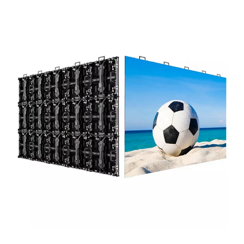
Unlike conventional SMD displays, COB panels do not behave like isolated point light sources. Instead, they behave more like continuous surface emitters with optical diffusion layers. Once engineers combine this with P1.25 or smaller pixel pitches, standard LED calibration methods no longer work reliably.
Below is the complete engineering workflow used in modern high-end COB calibration systems.
The industrial camera is the core component of the entire calibration system.
A 4K COB display contains millions of densely packed pixels, so the camera must capture extremely fine brightness and color variations with high precision.
| Parameter | 4K COB Calibration Requirement | Recommended Specification |
|---|---|---|
| Resolution | Must capture fine module-level detail | ≥12 MP |
| Sensor Type | High sensitivity for low-gray capture | ≥1-inch sensor |
| Dynamic Range | Preserve low-gray details | ≥12-bit (14-bit preferred) |
| Spectral Response | Match human visual perception | CIE 1931 XYZ calibration support |
| Data Interface | Handle massive real-time data | 10GigE / Camera Link / CoaXPress |
| Lens Type | Minimize distortion | Telecentric or ultra-low distortion lens |
Typical high-end sensors include:
with resolutions around 4096×3000.
A 4K COB display often uses pixel pitches smaller than P1.25.
For example, a single module measuring 320×180 mm may already contain over 25,000 pixels.
To achieve accurate calibration, engineers generally require:
Each LED emitting area must occupy at least 3×3 camera pixels.
This follows Nyquist sampling principles and allows the system to properly detect:
Without sufficient optical sampling density, calibration accuracy drops dramatically.
One camera cannot usually capture the entire 4K display at sufficient precision.
Therefore, calibration systems rely on precision motion platforms.
Typical configurations include:
These systems require repeatability better than ±5 μm.
When scanning large displays, the system captures multiple overlapping image regions and later stitches them together computationally.
To ensure reliable stitching:
COB low-gray calibration is extremely sensitive to ambient light.
Therefore, calibration normally takes place inside a controlled darkroom with:
Even tiny stray reflections can distort low-brightness measurements.
This is the single biggest difference.
| Characteristic | SMD LED | COB LED |
|---|---|---|
| Emission Type | Point light source | Surface light source |
| Pixel Boundary | Sharp and clear | Soft and diffused |
| Optical Behavior | Near-Lambertian | Affected by resin curvature |
| Low-Gray Appearance | Visible points | Smooth surface emission |
Traditional SMD calibration algorithms depend heavily on locating the center of each LED package.
That method fails with COB.
Because COB uses continuous phosphor and encapsulation layers, the light spreads across neighboring regions. Pixel boundaries become blurred rather than sharply defined.
Instead of center-point detection, COB calibration systems use:
These methods estimate the effective optical center of each pixel more accurately.
Additionally, uneven phosphor thickness may create internal brightness gradients within a single pixel area.
Therefore, algorithms often calculate weighted regional averages rather than relying on single-point measurements.
COB contrast performance depends heavily on PCB surface blackness.
However, different PCB batches often exhibit noticeable color variation.
Some substrates may exceed:
ΔE > 3
even before illumination begins.
Therefore, modern calibration systems also capture:
The algorithm then compensates not only for emitted light, but also for background surface reflectance.
This becomes especially important in high-contrast HDR applications.
Direct single-shot calibration of an entire 4K COB display is usually impractical.
Instead, engineers use a hierarchical workflow.
The camera captures individual modules at close range.
Typical distance:
At this stage, the system generates:
The camera moves farther back and captures multiple cabinets simultaneously.
Typical distance:
This stage corrects:
Finally, a wide-angle system captures the entire display.
Typical distance:
This stage compensates for:
Sometimes even high-resolution cameras cannot fully resolve tiny COB pixels.
In these cases, engineers use computational super-resolution techniques.
Methods include:
The camera physically shifts by fractions of a pixel between exposures.
Software then reconstructs higher-resolution brightness distributions computationally.
This significantly improves precision without requiring prohibitively expensive sensors.
The system first establishes pixel-to-pixel mapping between:
Engineers usually use chessboard calibration targets combined with distortion correction.
For COB’s blurred optical edges, the system applies:
to identify pixel regions accurately.
For each LED pixel, the system captures:
Using HDR multi-exposure imaging covering:
This preserves both highlight and shadow information.
Industrial cameras do not directly output true chromaticity values.
Therefore, engineers calibrate the camera response using:
This converts sensor RGB data into CIE XYZ color space.
The system generates calibration lookup tables for every pixel.
The algorithm typically normalizes all pixels relative to the dimmest acceptable reference point.
The system adjusts RGB gains to align pixels with the target white point and color temperature.
Because COB encapsulation layers are continuous, adjacent pixels influence each other optically.
This creates optical crosstalk.
To correct it, advanced systems apply:
to separate overlapping light contributions.
This step is critical for ultra-fine-pitch displays.
After generating correction coefficients, the system uploads them into:
The display then undergoes verification testing.
Typical performance targets include:
| Metric | Target |
|---|---|
| Brightness Uniformity | ≥95% |
| Chromaticity Consistency | ΔE ≤ 1.5 |
| Low-Gray Linearity | No visible stepping below 32 grayscale |
For comparison, uncalibrated displays often show only 70–80% brightness uniformity.
| Challenge | Root Cause | Engineering Solution |
|---|---|---|
| Low-gray flicker | Poor low-current consistency | Synchronize exposure with refresh cycles |
| Viewing-angle color shift | Resin refraction effects | Multi-angle LUT compensation |
| Thermal drift | Temperature rise during calibration | 30-minute thermal stabilization |
| Moiré patterns | Sensor grid interference | Slight camera tilt or optical LPF |
| Massive 4K data volume | Huge per-pixel LUT size | Lossless compression and real-time decompression |
Traditional SMD calibration focuses mainly on discrete point-source correction.
COB calibration must additionally manage:
Once engineers combine these factors with millions of pixels in a 4K display, calibration becomes a multidisciplinary system involving:
This is why high-end COB calibration systems remain one of the most technically demanding areas in the LED display industry today.
 EN
EN
 AR
AR
 BG
BG
 HR
HR
 CS
CS
 DA
DA
 NL
NL
 FI
FI
 FR
FR
 DE
DE
 EL
EL
 HI
HI
 IT
IT
 JA
JA
 KO
KO
 NO
NO
 PL
PL
 PT
PT
 RO
RO
 RU
RU
 ES
ES
 SV
SV
 TL
TL
 ID
ID
 SR
SR
 UK
UK
 VI
VI
 ET
ET
 HU
HU
 TH
TH
 TR
TR
 FA
FA
 AF
AF
 MS
MS
 GA
GA
 HY
HY
 AZ
AZ
 MN
MN
 UZ
UZ