Installing an irregular LED display is not a simple mounting task. It requires a coordinated approach that combines mechanical engineering, electrical design, and software calibration. Unlike standard flat screens, irregular LED displays demand precision customization and structural stability at every stage.
This guide walks you through a complete installation workflow, from planning to final acceptance, with practical tips for different screen types.
Phase 1: Pre-Installation Planning & Structural Setup
1. Site Survey and Detailed Design
Start with a comprehensive site inspection. Measure everything precisely and evaluate:
- Load-bearing capacity of walls or floor
- Ambient temperature and humidity
- Power supply locations and routing paths
Next, align with the manufacturer’s documentation:
- Structural drawings
- Pre-numbered LED modules (e.g., “Top-left curved module A-01”)
This numbering system allows installers to position each module accurately without guesswork.
2. Steel Structure and Frame Installation
The supporting structure defines the entire screen’s reliability. You must ensure extreme precision during installation.
Key requirements:
- Use laser levels and 3D measurement tools
- Control tolerance within ≤ 0.5 mm
Installation Tips by Screen Type
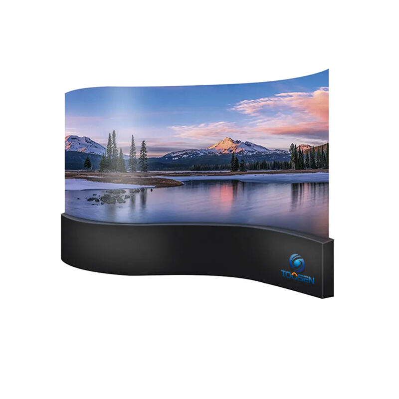
Curved / Wave Screens
- Match the exact curvature radius from the design
- Avoid forcing modules into position
Excessive stress can cause deformation or LED failure
Spherical LED Screens
- Divide the structure into upper and lower hemispheres
- Fix the lower structure with expansion bolts (≥ 15 cm deep)
- Suspend the upper structure using ceiling rigging
- Minimum: 3 suspension points per m²
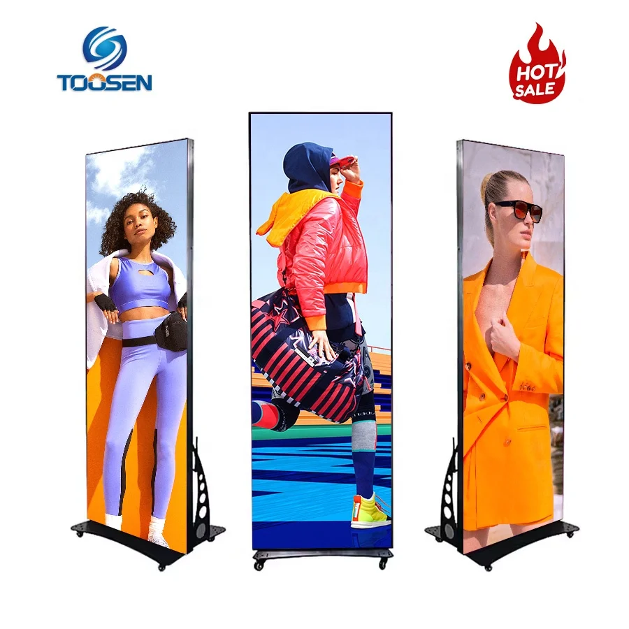
Column / Pillar Displays
- Build a reinforced concrete foundation first
- Install steel columns after curing
- Ensure proper grounding:
Phase 2: Module Installation & Wiring
1. Installing LED Modules and Cabinets
Different irregular displays require different installation techniques.
Flexible LED Modules (Curved, Cylindrical, Wave)
- Use magnetic mounting or flexible backing strips
- Install from one direction (bottom-up or side-to-side)
- Press modules firmly using rollers to eliminate air gaps
Critical constraints:
- Minimum bending radius (e.g., R200mm / R500mm)
- Maximum bending angle: ≤ 90°
Never over-bend modules—this is a leading cause of failure.
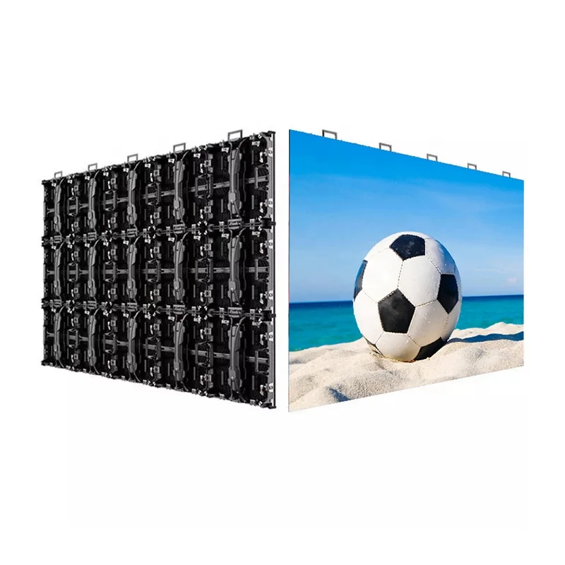
Spherical / Polygonal Cabinets
- Use custom-shaped cabinets (triangular or trapezoidal)
- Pre-install power supplies and receiving cards inside cabinets
Installation sequence:
- Assemble layer by layer (ring-by-ring)
- Check alignment after each layer
- Maintain seam gaps ≤ 2 mm
Offset and Rotated Installations
Irregular screens often require:
- Offset placement
- 90° rotation
Focus only on secure physical installation at this stage.
You will correct visual alignment later through software.
2. Power and Signal Wiring
Distributed Power Design
Avoid centralized power systems.
- Place power supplies close to load نقاط
- Reduce voltage drop over long distances
Anti-Interference Wiring
- Separate power and signal cables (≥ 10 cm فاصلة)
- Route signal cables along steel structure
- Keep them away from high-voltage lines
For long-distance transmission:
- Use fiber optics or shielded Ethernet cables
This prevents:
- Signal interference
- Screen flickering or blackouts
Phase 3: Software Configuration & Image Calibration
Once powered on, irregular LED screens rarely display correctly at first. You will likely see:
- Image tearing
- Misalignment
- Distortion
This is normal. Now you transition into software correction.
1. Initial Setup
- Connect the control system to a computer
- Use professional software such as:
Import the screen configuration file.
For rotated modules:
- Enable rotation settings (e.g., vertical scanning or angle adjustment)
2. Cabinet Mapping (Pixel Mapping)
Use the “Cabinet Construction” or “Irregular Screen Editing” tools.
Process:
- Follow the actual physical wiring order
- Manually map each module
- Define pixel connections and sequence
Accuracy here directly affects display integrity.
3. Position Fine-Tuning
Fix physical misalignment digitally:
- Select individual modules
- Adjust position using keyboard or mouse
Use test patterns:
- Crosshair lines
- Grid lines
Goal: seamless continuity across the entire screen
4. Geometric Correction & Color Calibration
Geometric Correction
For curved or spherical screens:
- Apply content warping (reverse distortion)
- Prevent stretched or skewed visuals
Color and Brightness Calibration
Edge modules often appear inconsistent due to viewing angles.
- Perform pixel-level calibration
- Adjust brightness and chroma individually
This ensures uniform visual output.
Phase 4: Final Inspection & Acceptance
Before handover, conduct a full system validation.
1. Visual Testing
Run multiple test scenarios:
- Solid colors (Red, Green, Blue, White)
- Grayscale gradients
- Dynamic video content
Check for:
- Dead pixels
- Dark spots
- Color banding
- Flickering
2. Safety Inspection
Verify:
- All screws and fasteners are secure
- No exposed wiring
- Grounding system is properly connected
3. 72-Hour Aging Test
Run the screen continuously for 72 hours.
Monitor:
- System stability
- Thermal performance
- Hotspot areas (especially corners and tight angles)
Pay close attention to heat accumulation zones, which are common in irregular structures.
Conclusions
Irregular LED display installation is fundamentally different from standard screens. It requires:
- Precision engineering
- Careful sequencing
- Advanced software correction
If you execute each phase correctly, you will achieve:
- Seamless visuals
- Long-term reliability
- Safe operation
In irregular LED projects, success depends on both physical accuracy and digital calibration.
Key Takeaways
- Always start with precise site measurement and structural design
- Maintain strict tolerance control (≤ 0.5 mm)
- Respect module bending limits to avoid damage
- Use distributed power and interference-safe wiring
- Rely on software for final alignment and correction
- Perform full testing, including a 72-hour aging run
 EN
EN
 AR
AR
 BG
BG
 HR
HR
 CS
CS
 DA
DA
 NL
NL
 FI
FI
 FR
FR
 DE
DE
 EL
EL
 HI
HI
 IT
IT
 JA
JA
 KO
KO
 NO
NO
 PL
PL
 PT
PT
 RO
RO
 RU
RU
 ES
ES
 SV
SV
 TL
TL
 ID
ID
 SR
SR
 UK
UK
 VI
VI
 ET
ET
 HU
HU
 TH
TH
 TR
TR
 FA
FA
 AF
AF
 MS
MS
 GA
GA
 HY
HY
 AZ
AZ
 MN
MN
 UZ
UZ