Home > News > Industry News
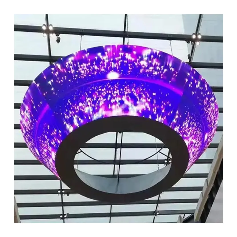
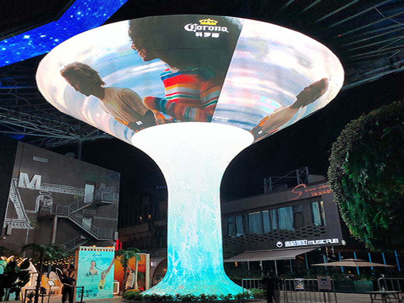
Installing a cylindrical LED display or suspended ring-shaped LED screen involves far more than simply hanging a display from the ceiling. These systems often weigh hundreds of kilograms and remain suspended above public spaces for years. As a result, structural safety, suspension design, and long-term maintenance accessibility must become top priorities from the very beginning of the project.
Whether the installation is located in a hotel lobby, shopping mall atrium, exhibition hall, or corporate showroom, proper engineering ensures both safety and long-term reliability.
This guide explains the most critical considerations for installing cylindrical and ring-shaped LED displays, focusing on structural load calculations, suspension systems, and maintenance access planning.
Unlike wall-mounted LED displays that transfer weight directly to a building façade, cylindrical LED screens rely entirely on overhead suspension systems.
A typical medium-sized cylindrical LED display with a diameter of 3 meters, a height of 5 meters, and multiple ring layers may include:
| Component | Typical Weight |
|---|---|
| Flexible LED modules and mounting frames | 150–250 kg |
| Main steel structure | 300–500 kg |
| Power supplies, controllers, and cabling | 50–100 kg |
| Total System Weight | 500–850 kg or more |
In practical terms, this means the ceiling structure may support a load comparable to a small automobile for many years.
For this reason, qualified structural engineers should always perform load calculations. Project teams should never rely on assumptions or rough estimates.
One of the most common installation mistakes occurs when contractors attach suspension systems to decorative ceiling components.
The following structures are not designed to support LED displays:
Instead, installers should anchor suspension systems directly to:
Only these structural elements can safely transfer long-term loads.
Before installation begins, the project team should:
The final engineering report should confirm that the structure can support:
Most suspended LED display projects follow these minimum guidelines:
| Requirement | Recommended Value |
| Static Load Safety Factor | ≥ 3× display weight |
| Dynamic Load Factor | 1.2–1.5× |
| Maintenance Load Allowance | Additional 200–300 kg |
These margins help ensure long-term structural safety.
The suspension frame serves as the primary connection between the building structure and the LED display.
Manufacturers typically fabricate these frames using:
Depending on project requirements, engineers may select:
Suitable for:
Recommended for:
Multi-point systems distribute loads more evenly and improve overall stability.
All welds should undergo inspection and receive anti-corrosion treatment before installation.
| Suspension Method | Best Application | Key Considerations |
| Rigid Suspension Rods | Lower ceiling heights | Requires precise vertical alignment |
| Steel Wire Ropes | High ceilings and adjustable installations | Must meet calculated breaking-strength requirements |
| Motorized Lifting Systems | Large displays requiring frequent maintenance | Higher cost but greatly improves serviceability |
For steel wire rope systems, engineers commonly specify 6×19 or 6×37 construction ropes because they offer excellent flexibility and strength.
Every suspended display should include backup protection systems.
Best practices include:
After installation, contractors should conduct a static load test using at least 1.5 times the display's operating weight and maintain the load for 24 hours.
Many projects focus exclusively on visual impact while overlooking future maintenance requirements.
However, even high-quality LED displays eventually require:
Without proper access, maintenance costs can increase dramatically.
Maintenance requirements directly influence structural design.
| Maintenance Type | Advantages | Recommended Conditions |
| Front Service | Simple module replacement from the display face | Displays within reach or accessible by scaffolding |
| Rear Service | Technicians access components from inside the structure | Ring diameter ≥ 1.5 m |
| Motorized Lowering System | Entire display descends for maintenance | Premium projects with sufficient budget |
For large cylindrical displays and multi-ring installations, rear access remains the most practical solution.
Engineers should provide:
These features allow technicians to work safely and efficiently inside the structure.
For large-scale or high-elevation installations, motorized maintenance systems can significantly reduce service complexity.
These systems typically include:
When maintenance is required, technicians can lower the entire display to a safe working height.
As a result, service operations become faster, safer, and less expensive.
Even when using front-service modules, designers should leave sufficient space for future repairs.
Recommended practices include:
Remote troubleshooting can significantly reduce the need for high-altitude maintenance work.
Before project handover, verify the following items:
| Inspection Item | Requirement | Responsible Party |
| Structural Calculation Report | Signed by licensed structural engineer | Design Consultant |
| Steel Structure Quality | Passed weld inspection | Manufacturer |
| Static Load Test | 1.5× design load for 24 hours | Installation Contractor |
| Suspension Hardware Certification | Matches engineering specifications | Supplier |
| Anti-Fall Protection | Installed at every suspension point | Installation Contractor |
| Grounding and Lightning Protection | Ground resistance ≤ 4 Ω | Electrical Contractor |
| Maintenance Access Acceptance | Meets safety standards | Owner / Consultant |
 EN
EN
 AR
AR
 BG
BG
 HR
HR
 CS
CS
 DA
DA
 NL
NL
 FI
FI
 FR
FR
 DE
DE
 EL
EL
 HI
HI
 IT
IT
 JA
JA
 KO
KO
 NO
NO
 PL
PL
 PT
PT
 RO
RO
 RU
RU
 ES
ES
 SV
SV
 TL
TL
 ID
ID
 SR
SR
 UK
UK
 VI
VI
 ET
ET
 HU
HU
 TH
TH
 TR
TR
 FA
FA
 AF
AF
 MS
MS
 GA
GA
 HY
HY
 AZ
AZ
 MN
MN
 UZ
UZ